|
||
|
|


|
|
Getting started with UML
If you're looking for some informations about UML, you're on the right page. If a few words, I will try to introduce what is UML and (I hope) why you should use UML. Don't expect some precise informations : I tried to produce an effective text.
What is UML ?
| UML is the acronym of Unified Modeling Language. It's a language invented to help to communicate upon object programming concepts that are not intuitive. UML was born in the middle 90's by merging three methods : OMT, Booch and OOSE. This is a graphical language composed by 13 diagrams (UML 2.0). UML is powerfull because these diagrams are always very friendly. It's an efficient way to communicate between programmers and end users. It can also be very precise and helps to avoid ambiguities when you define your system. |
What is it not ?
UML is not a method. (it's a common mistake). It's a language. So, UML will not help you to organize your project. It will just help you to describe it, to communicate over it, to clarify its features.
Let's introduce diagrams
The following informations are very important to understand how to use UML. It's probably the thing you must understand first. UML diagrams can be categorized in two main views :
- a static view
- a dynamic view
- Humm... I would like add an optional third view called physical view. I'll explain it later.
If you're looking for some presentations of UML on your favorite Google, you will find some other ways to classify UML diagrams. For example, some people prefer working with a structure view, a behavior view and a interaction view. The structure view corresponds to our static view. The behavior view and the interaction view are merged in our dynamic view. In my opinion, it's easier to understand a system using its static and dynamic dimensions.
The static view
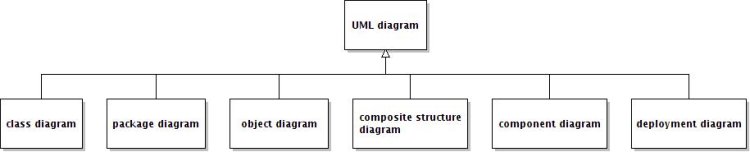
The static view contains diagrams showing all the entities and behaviors of your system. Let's go back to a fundamental object concept : an object is defined by its behavior and its state. Consider that an object is an entity. These diagrams would expose all your system entities, define their rules and how they will interact all together :
- the class diagram shows entities such as classes and interfaces, their content and relationships. It's the most popular diagram.
- the package diagram helps you to organize your classes in packages. It shows all the links between packages. So it helps you to see dependencies in your program. Never forget that a good programmer is always worried about reducing dependencies. It's the key to keep your code flexible. This advice is also usefull for the class diagram.
- the object diagram shows classes in a specific state. It's like a snapshot of your program running. (I'm not a fervent supporter of this kind of diagram.)
- the composite structure diagram allows to represent the internal structure of a complex object at runtime. It shows how it interacts with the system. I never used it in the Real World.
- the component diagram shows all you system components in term of database, web programs, middlewares, etc.... It is usefull overview of your system. I think that it's an important document to be communicated to system engineers.
- the deployment diagram is also an important document to be communicated to system engineers. It indicates where all components are deployed. So, you see which server is used, which IP address, etc...
The dynamic view
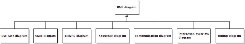
The dynamic view contains diagrams showing scenarios. This time, you see how entities works, not only how they are made. Let's introduce them :
- the use case diagram represents what your system should do. It's the first diagram you make when you start a project. It will help you to clarify and identity actors (end user, external systems, etc...) and all your system features. At this state, you don't think in term of implementation. So, never put a use case like "writing to database" or I call Chuck Norris!
- the state diagram was created to represent the different states of a machine. Each state is raised by an event. With this diagram, you can see your system state when something happens. For example, when I push the start button of my washing machine, its state is "starting washing program".
- the activity diagram is a very old diagram. It's a kind of flow diagram with branches and conditions. It is very easy to understand by end users. So, it's one of the most important UML diagrams
- the sequence diagram is my favorite. It shows a complete scenario with all the actors and how actions are chained. This sequence always starts with a first actor who wants to do something. Then, it triggers an action on the next actor and so on. The sequence diagram is excellent to describe a system works. I love it! (really!)
- the communication diagram is globally another way to represent things you drew on a sequence diagram.
- the interaction overview diagram is a form of activity diagram where each nodes represent a sub diagram (an activity diagram for example). It's like a zoom out of your system.
- the timing diagram is used to display state changes of elements over time. Honestly, I've never tried it. I think that it could be usefull to describe real time systems (like eletronical systems)
The (mysterious and very personal) physical view
I wrote previously about a "physical view". This view is composed by :
- the component diagram.
- the deployment diagram.
Want to add a link to this site on your web page? Please, do not copy-paste current url. Use http://violet.sourceforge.net instead.
Powered by FCKwiki, the wiki for programmers developed by Alexandre de Pellegrin.